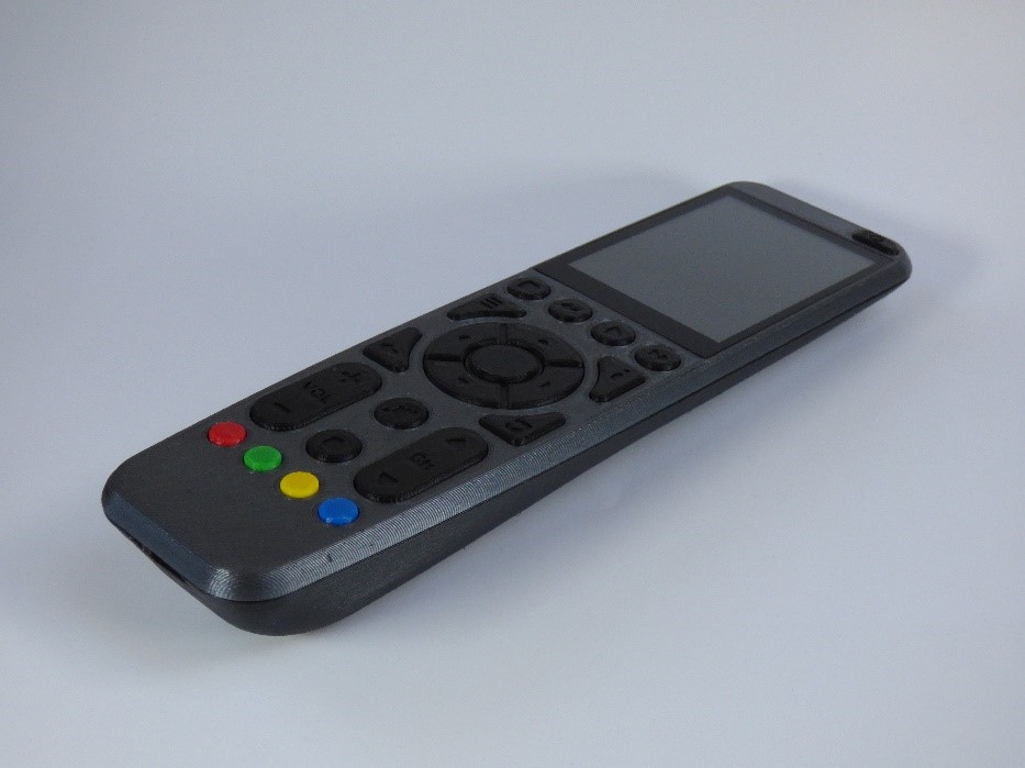
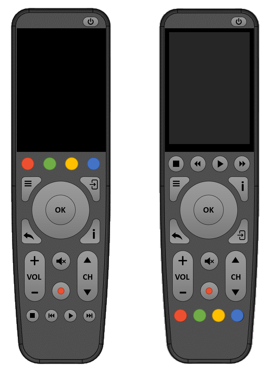
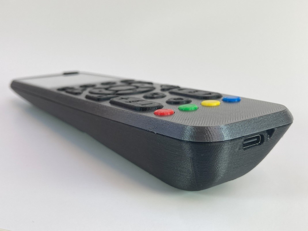
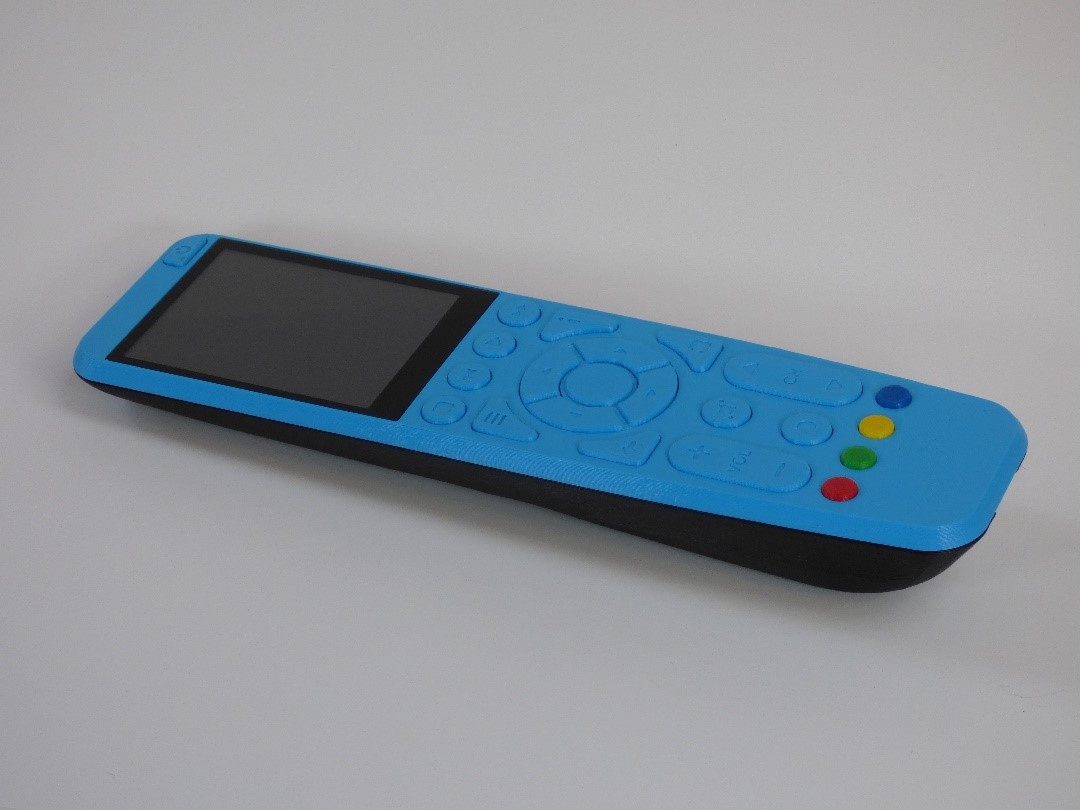
Close
0%
0%

OMOTE - DIY Universal Remote

Open-Source Infrared Remote Using ESP32 and LVGL

Similar projects worth following
OMOTE is an ESP32 based open source universal remote. Its capacitive 2.8” touchscreen provides an intuitive and snappy user interface for switching devices and settings. No hub or docking station is required as the remote features infrared, Wi-Fi and Bluetooth connectivity. With its well optimized power consumption, OMOTE can run for months on a charge. And since the design files are open source, you can fully customize them to your devices and needs.

Some of the key features:
• 2.8” 320x240px capacitive touchscreen
• Ergonomic, fully 3D printed case
• Responsive LVGL user interface
• Built in infrared, Wi-Fi and Bluetooth
• Press any button or simply lift the remote to wake it up
• Up to 6 months of battery life using a 2000 mAh Li-Po battery

Layout files, code and STLs on GitHub: https://github.com/CoretechR/OMOTE

Logitech surprisingly discontinuing its popular line of Harmony remotes left many owners of home entertainment systems seeking alternatives. While there are some new competitors, their ergonomics and battery life still leave room for improvement. To me, a DIY version of a universal remote seemed like a nice project that combines ergonomic design with low power and graphical interfaces.

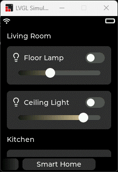
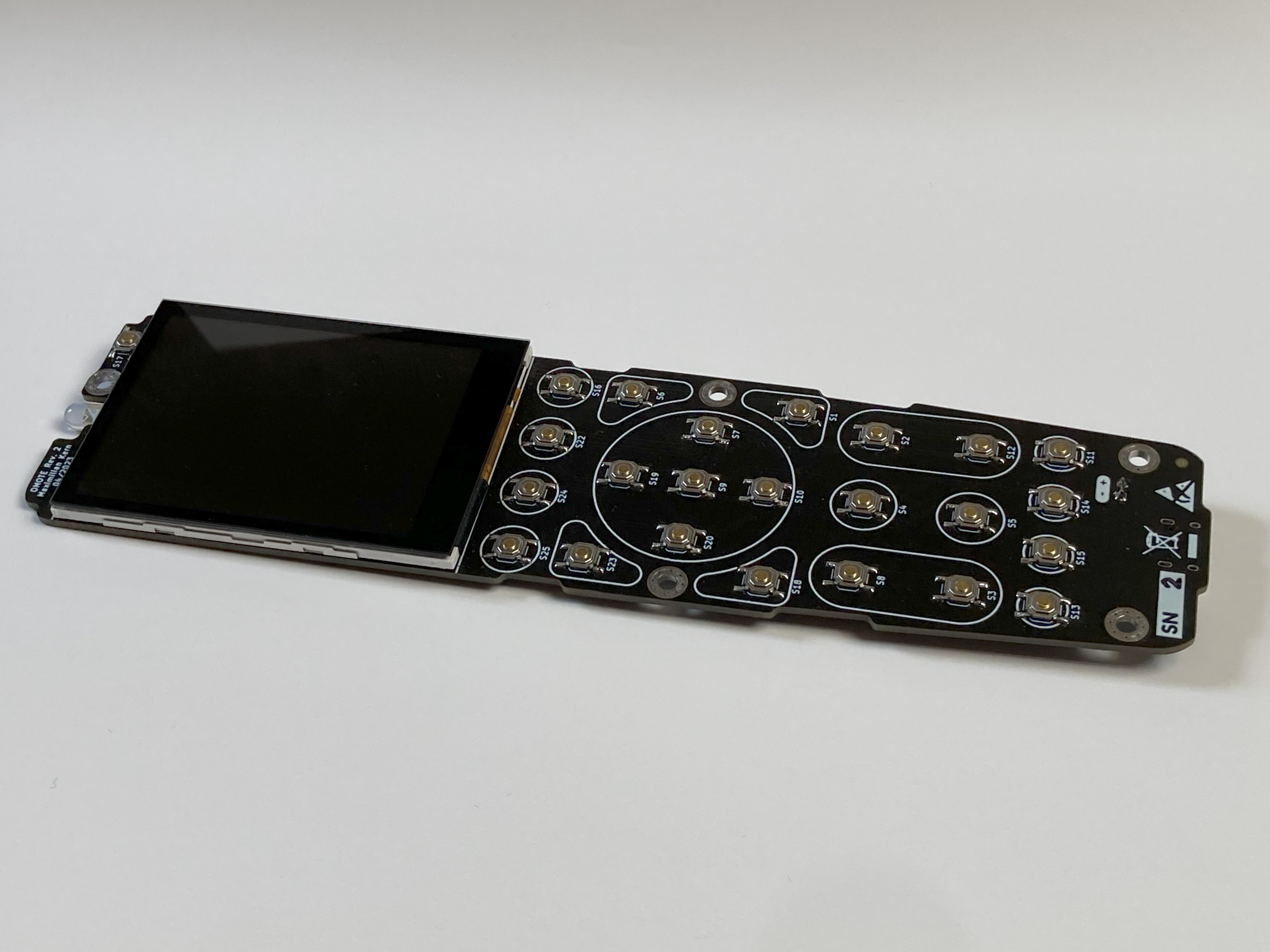
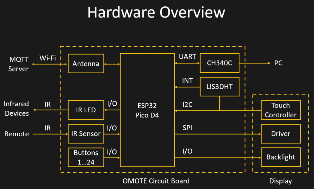
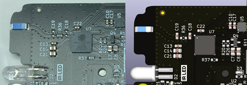
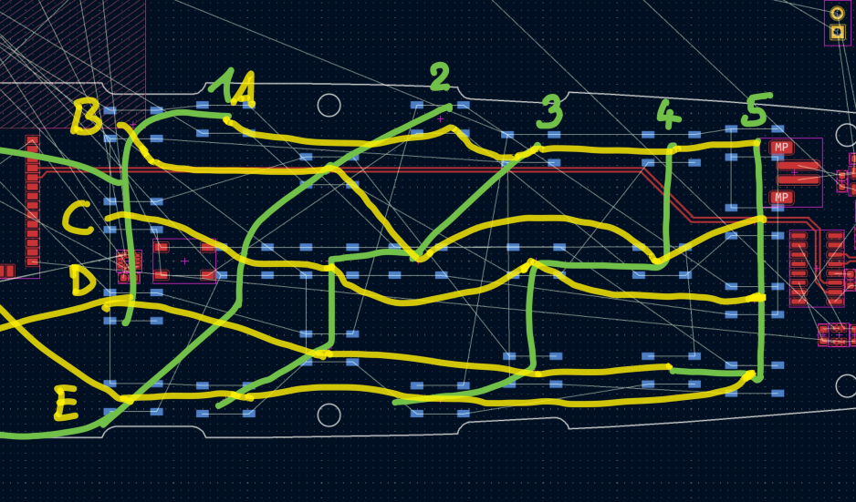
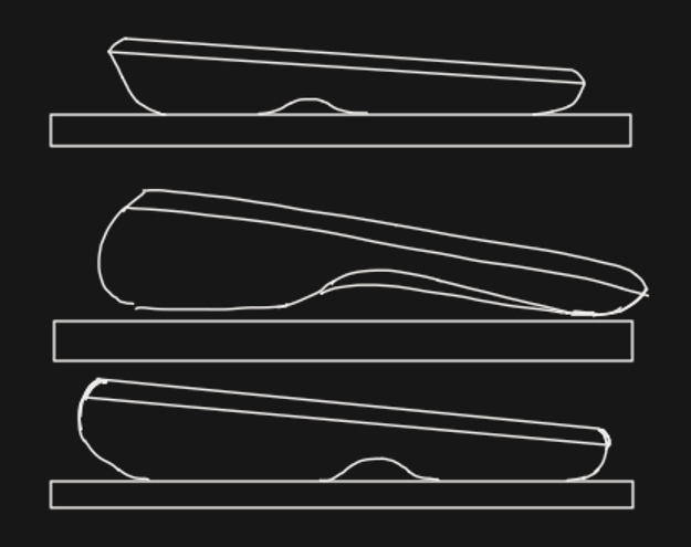
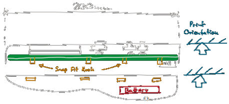
While building a device that sends infrared codes seemed simple enough, it was challenging to optimize it for 3D-printing and still have it look like a commercial product. Running a touch-based UI on an ESP32 and making it responsive was also no easy task. If you want to find out more about this project, check out the project logs below.

  • Software

    Max.K07/01/2023 at 08:46 0 comments

    One of the reasons for starting this project was that I wanted to try out LVGL. LVGL is an open-source embedded graphics library that is well optimized to run on microcontrollers like the ESP32. You can create user interfaces using a set of building blocks like buttons and sliders and add styles and animations to them. With little effort these UIs end up looking beautiful and professional. There is even a drag and drop editor, Squareline Studio, that generates the necessary code for you. To be more flexible, I decided to start with the LVGL simulator for Visual Studio.

    For my universal remote interface, I am using multiple pages, that can be scrolled through by swiping horizontally. Each device has its own page that contains the corresponding buttons. There is a larger settings page, that can also be scrolled vertically. These pages are set up as a “tabview” object so they behave like a smartphone home screen. Everything about the scrolling and animations is then handled by LVGL. I also added a little page index to the bottom that contains the pages title. These text boxes fade out to the sides using transparent bitmaps, as a reference to the iOS camera app.

    After building and testing the interface on my PC, I copied the code over to Platformio for the ESP32. The touch buttons can then be mapped to sending infrared signals using event callback functions. Display output and touchscreen input is connected to LVGL using the TFT_eSPI and Adafruit FT6206 libraries.

    The interface looks nice and sharp even on the 320 by 240 pixel display. UI elements like sliders were working fine immediately at around 30 fps. Only when scrolling the pages, I experienced drops in framerate (9-10 fps) and visible lag at first. Luckily LVGL and TFT_eSPI support DMA and double buffering, meaning that the ESP32 can draw one frame, while the other is sent to the display simultaneously. This takes up more RAM, but it increased the frame rate during scrolling to nearly 20 fps. SPI frequency has a huge impact as well. On paper, the ILI9341 display driver only support SPI frequencies of around 6MHz, but it usually works even at 80MHz. I have had displays that would only work at up to 40Mhz, which leads to a slightly lower performance.

    For many of the additional hardware features, I am using Arduino libraries. “IRremoteESP8266” deals with the infrared sending and receiving. It supports basically any manufacturer’s standard. The LIS3DH accelerometer detects when the device is in motion. I am using Sparkfun’s library to read the acceleration values and to configure the interrupt for waking up the ESP32. Another wakeup source is the tactile button grid. This is handled by the Keypad library which I modified to invert its logic. This way I can use the ESP32’s EXT1 wakeup to detect if the accelerometer pin or any button pin goes high. Booting the ESP32 takes around half a second from the interrupt to the point where the display is turned on.

    When the motion detection is used, the display usually turns on before I have a finger on a button.

    To make use of the 2.4GHz antenna, I created another UI page for smart devices. This way, the remote can control lightbulbs by communicating with my MQTT server over Wi-Fi.

    Right now, the IR codes and button mapping is hard coded for my personal use. A next step would be making the interface configurable. This could be done on the remote itself by expanding the existing touchscreen UI or on a computer using for example a HTML interface that is hosted by the ESP32.

  • Electronics

    Max.K07/01/2023 at 08:43 0 comments

    Because of its wireless interfaces and low power consumption in sleep mode, the ESP32 is an ideal choice for this project. I included a CH340C serial adapter, so it can be programmed using a USB Type-C port. The same port can also be used for charging a Lithium-Ion battery by including a charging IC.

    While the display is powered up and the ESP32 is not in sleep mode, the device quickly drains the battery. To minimize the time in this active mode, a LIS3DH 3-axis accelerometer can detect if the device is moving. Via i2c the ESP32 can check if it stopped moving for a while and power down. An additional interrupt pin wakes the controller as soon as the remote is picked up again.

    To save on IO pins, the 24 tactile switches are arranged in a 5x5 grid. Each row is connected to a digital input while the columns are constantly toggled in software. This way, only 10 instead of 24 pins are needed. The five input pins can also be used to wake the device up from sleep. For this, they need to use the same logic (active high) as the accelerometer interrupt and the five outputs must remain High.

    The display is connected to the controller via SPI for the pixel data and i2c for the touchscreen. I am using the ESP32s hardware SPI pins to take advantage of the full 80MHz that the controller supports. The displays backlight can be turned on by a DMG2301 MOSFET. Another one of these MOSFETs is used to switch of the display logic and touch controller since they draw some power as well.

    A third MOSFET is used to control the infrared LED. It uses a very small, 3.3 Ohm series resistor to maximize its range. A Vishay TSSP77038 IR Sensor enables it to read and decode commands from other devices.

    I had already created the basic outline of the PCB in Fusion360, so I simply imported it directly into KiCad. A major challenge was placing the Wi-Fi antenna in such a way, that it is not obstructed by the metal display frame or the hand that holds the remote. The only possible location was the top corner of the PCB, right next to the IR LED. I had used the ESP32-WROOM module previously, but it was too big to fit and half the pins would end up on the edge of the PCB. Instead, I switched to the ESP32-PICO-D4. It’s a 4x4mm System-On-Package that contains most of the components of the WROOM module. An external antenna, like in this case a small chip antenna, can easily be connected to the Pico. Trace antennas would also be an option, but chip antennas usually are more robust against influences like the 3D printed case. The trace line between the ESP32 and the antenna should normally be impedance controlled which is tricky on a 2-layer PCB. I can get away with this by keeping the length below 1/10 of the wavelength (12mm for 2.4GHz). I also ensured that there is a continuous ground layer below the trace line and ESP32 and that vias are placed along the edges.

    I am using a regular 5mm infrared LED that is soldered to the top edge of the board. The IR receiver is placed next to it. A 40 Pin connector is used for the display, while its cable goes through a cutout in the PCB. Another cutout makes room for the touch controller that protrudes the display cables. This allows the display to be glued flat on the PCB. On the lower end of the PCB, there is room for the USB Type-C connector, the serial adapter and the charging IC. The only components on the other side of the board are the tactile switches. For the button matrix to work, these switches need to be arranged in a 5x5 grid. It was a little tricky figuring out the placement so the traces don’t cross.

    Since the ESP32-PICO-D4 only has pins on the bottom, it needs to be reflowed. Luckily, I have a small hot plate that I could put to proper use for the first time. Since the hot place is only 3x3cm, I had to move the board around during soldering. For solder paste, I used the MECHANIC XGZ4 and set the plate to around 220°C. As this was my first try at reflow soldering, I was amazed at how clean the solder...

    Read more »

  • Hardware

    Max.K07/01/2023 at 08:31 0 comments

    My initial idea was to build a universal remote with both a touchscreen as well as physical buttons. For communication the remote would need an infrared LED and optionally an RF module for Wi-Fi and Bluetooth. Like in most of my previous projects, I wanted to use common, off-the-shelf components and 3D-printing so anyone can build the remote themselves.

    For the display I picked a 2.8” screen from Adafruit with a built-in capacitive touchscreen. Adafruit sells these displays either standalone or on a breakout board. There is also a slightly cheaper version that has a resistive touchscreen. But in my opinion capacitive touch feels nicer for this type of device and the screen is also more durable due to the glass surface.

    The size of the screen defines the overall dimensions of the remote. I ended up with roughly 20x5cm.

    I started by drawing some sketches to figure out the best shape for the remote. To make 3D printing easier, I wanted to keep the top of the remote completely flat. This way the case can be split into two parts. The top part can be printed with the flat outer surface facing the print bed. The larger, lower part will be printed on the separation plane with the inside facing down. This way elements like snap fits can be printed that protrude this separation line.

    For the buttons I wanted to have the most common media and navigation keys that are needed to control a TV. This includes four-way keys, playback control, four color keys and a few more buttons for functions like input select and menu navigation.

    Based on these sketches I went on to create a first concept in Fusion360. It is designed around the large display, so the case is flat and wide at the top. Towards the bottom the remote is tapered and thicker, so it can be held comfortably. A small indent is where the index finger goes, so the thumb automatically lands on the OK button. I printed this first draft to test how the shape looks and feels. Since I happy with it, I barely changed the design but only added more details to it. This included splitting the case into two hollow halves and adding ribs for stability. One of the main challenges was fitting the halves together as I did not want to rely on visible screws. I experimented with small snap fitting hooks but they broke off too easily. Instead, I went with a lip and groove joint that goes around the entire edge of the device. On the sides there is a slight undercut so the parts interlock but can be separated with little force. This obviously means that the 3D printer must be well calibrated or the parts will not fit at all.

    Most commercial remotes use silicone keypads but due to the cost of the required molds, this is impractical for DIY projects. I decided to use regular tactile switches and 3D printed button caps instead. I tried to keep the labels simple, so they could be embossed into the button’s surface. With a 0.4 mm nozzle, these came out fine on my printer.

    For the printed parts, I used matte black PETG filament from ColorFabb and Anthrazit PETG from Dasfilament. I also experimented with a flashier color theme using Colorfabb’s light blue NGEN filament. As the front cover is only snapped into place, it is easily replaceable.

View all 3 project logs

Enjoy this project?

Share

Discussions

Martin wrote 03/02/2024 at 14:42 point

Very good idea 👍

  Are you sure? yes | no

Michil783 wrote 10/28/2023 at 16:44 point

Hello,

the branch „abstraction“ got a great improvement on SW side. My C++ experience is a bit older and it would be great if the contributory could spent some documentation like class diagrams or ideas behind the changes.

What I‘m personally missing is a status bar, e.g. On top of the screen which displays the battery status, USB connectivity, … .

I would like to add this but an existing class diagram would help here, especially for me because I have to relearn C++ again.

Kind regrads

Michael

  Are you sure? yes | no

KawalkQWCki wrote 10/25/2023 at 09:49 point

Use TSAL6102UL (+/-10degg beam) or VSLY5940 (+/-3 deg beam) as the IR emitters as they  have much higher power output.  The 5940 is insane powerful but need  a lot more of them for wide coverage.  I would use a min of 3 6102UL emitters. Logitech uses a few emitters for better coverage. Also connect the driver mosfet and emitters to battery voltage or 5V and not 3.3V .I would use a N type mosfet on the ground side and  not P type to control the IR . 

  Are you sure? yes | no

rens_wildeboer wrote 09/07/2023 at 09:00 point

Truely a work of art, I worship your skills and ability. I believe you have thought of everything and your solutions to mitigate issues are impressive.

Great work mate

  Are you sure? yes | no

Max.K wrote 09/29/2023 at 18:25 point

Thank you very much for the kind words!

  Are you sure? yes | no

RoboticWorx wrote 08/23/2023 at 02:08 point

This is very cool. Great project!

  Are you sure? yes | no

Max.K wrote 08/26/2023 at 22:18 point

Thank you!

  Are you sure? yes | no

Mehrdad Majzoobi wrote 07/26/2023 at 22:46 point

would love to collaborate with you on this project. We can use Ubo Pod (https://hackaday.io/project/190742-ubo-pod-build-apps-with-rich-ux-on-raspberry-pi) as the hub to run home assistant on it and interface with OMOTE. Ubo Pod also has IR receive and transmit functions. Also, I had a few suggestions: It will be more cost-effective and easier to manufacture the remote buttons with silicon keypads with carbon coating. They are quite cheap to make at volume and you don't need to 3D print or injection mold every button. I can also help with mass production since I am in China a few times a year and already work with several CMs there. Anyways you can reach me via email mehrdad at getubo dot com 

  Are you sure? yes | no

Paul wrote 07/21/2023 at 05:54 point

Awesome project!  I've lost count of the number of remotes I have.  I'd buy a populated PCB - that would be ideal, but willing to give it a go with a bare PCB and parts list 

  Are you sure? yes | no

Max.K wrote 07/23/2023 at 17:53 point

Thanks, if you want the PCBs, you can keep an eye on this GitHub issue: https://github.com/CoretechR/OMOTE/issues/3

  Are you sure? yes | no

bshiff wrote 07/20/2023 at 17:35 point

This is a wonderful project - well done!!!  I'd also buy at least a couple PCBs if they were made available.

  Are you sure? yes | no

scottnicholascook wrote 07/18/2023 at 06:21 point

Yes please on the PCB's

  Are you sure? yes | no

eitch wrote 07/17/2023 at 11:47 point

Yeah, i am also interested in buying a populated PCB, as i don't think i can every solder that myself. But i would even buy a few, as these remotes make it seem perfect to have one lying around in every room, to control wireless bulbs etc.

  Are you sure? yes | no

Vission01 wrote 07/16/2023 at 20:37 point

Another vote for selling populated pcb's!

  Are you sure? yes | no

patrick wrote 07/16/2023 at 19:51 point

would be very interested for a fully populated PCB as well!

great project, and will continue to follow. still looking for the perfect replacement for my logitech remote

  Are you sure? yes | no

Craig Hissett wrote 07/16/2023 at 00:00 point

This is wonderful! I love the blend of remote and also smart home controller.

I'd love to have one of these tied into my HomeAssistant setup.

  Are you sure? yes | no

Max.K wrote 07/17/2023 at 16:08 point

Thank you, Craig!

  Are you sure? yes | no

rainae wrote 07/15/2023 at 11:54 point

If one could buy the pcb's would be great!

  Are you sure? yes | no

gacekk wrote 07/15/2023 at 09:25 point

Definitely you should start selling PCBs asap

  Are you sure? yes | no

jp wrote 07/15/2023 at 03:43 point

This is terrific - I can handle the 3D printed part, and some through-hole soldering, but I'm not going to be able to invest in the necessary equipment for SMT soldering - any chance you would offer the PCB and components ???

  Are you sure? yes | no

rg wrote 07/14/2023 at 08:36 point

Wondeful project!
But it outperforms my abilities - so is it commercially available?

  Are you sure? yes | no

Max.K wrote 07/14/2023 at 18:50 point

Thank you! It is not for sale in any form right now. But since many people seem to be interested, at least the PCBs could be made available at some point.

  Are you sure? yes | no

Plastic-armyman wrote 07/16/2023 at 18:12 point

Yes please! I would for sure get a PCB and build one of these myself.

  Are you sure? yes | no

bpwtk wrote 09/11/2023 at 06:08 point

You have worked with it, many people would be interested. Can I ask why you don't sell it in full kit if everything is done. Why don't you do business?

  Are you sure? yes | no

Michil783 wrote 10/10/2023 at 10:40 point

Hello Max,

it‘s really a great project and I tried to make the PCB by myself (at least the soldering) but I was not successfull. So I ordered the fully (nearly fully but without the switches) populated PCB at JLCPCB. Hope that this will work. I‘m interested to develop SW for it. If the board is working, I will have 4 pcs left because min ordering was 5 pcs. Btw, I have some unpopulated PCBs from OshPask (purple PCBs) left. 

Kind regards

Michael

  Are you sure? yes | no

Max.K wrote 10/10/2023 at 19:03 point

@Michil783 Hi Michael, thanks, I hope the finished PCBs will work for you. Have you seen the Discord channel? You can surely find a buyer for the leftover PCBs there, especially if you're from Germany. Best, Max

  Are you sure? yes | no

Similar Projects

Does this project spark your interest?

Become a member to follow this project and never miss any updates